The device is designed based on a maximum yield stress, a corresponding magnetic field, a torque and the MR fluid viscosity. With proper knowledge of these parameters the dimensions of the device components can be determined. The Minimum Active Fluid Volume (MAFV) technique is used for designing the device. MAFV is the volume necessary to meet the performance specifications of the design. Specifically it is the volume that will be affected by the magnetic flux. It depends on the fluid's dynamic range, the fluid's coefficient and mechanical power dissipation. The dynamic range is a parameter that determines how much the resistant torque increases when the fluid is activated. Mathematically, it is the quotient of smallest and largest possible values of the resistant torque. For the MAFV, the fluid viscosity and the yield stress of MR fluid are needed. These properties can easily be found from tabular data. The MAFV is formulated by
![]()
where k, Wm ,eta, lambda, and tau(y) represent the fluid's constant, mechanical power, dynamic range, viscosity, and dynamic yield stress. With two magnets on each side, total of four magnets for the device, the device is designed to achieve a resistance torque of 30 Nm. As the person extends his/her leg the plates of the device that are directly attached to the shafts which are connected to the leg rotate accordingly as well as experience an opposing torque from the sponge. Figure 1 depicts how the device is supposed to fit the user's leg. As can be seen it fits the same way as an ordinary knee brace.
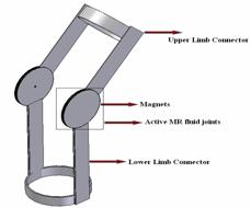
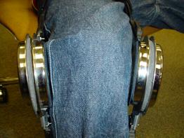
Fig1: Schematic of the proposed MR fluid-based knee brace and a View of that
Our experimental analysis is based on experiments done using an MTS machine. With the MTS machine we induced compressive forces on the shafts of the device which in turn produces a torque on the MR sponge. Feedback from the device was recorded from the MTS machine and plotted in a computer program. The program gives information about many things but we extracted data about maximum torque and torque over a range of motion.
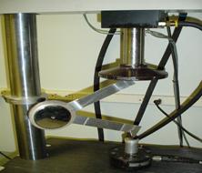
Figure 2: (a) Knee brace test using MTS machine, (b) Torque vs. displacement plots