Spiral patch antennas are inherently broadband in both directions. In many applications however, radiation is only needed in one direction. To eliminate radiation in the unwanted direction, a ground plane is usually employed on that side of the antenna. This ground plane eliminates the problem associated with radiation in two directions. However, in doing so it eliminates the broadband effectiveness of the antenna.
Basic calculations show that once the ground plane has been added, the wavelength (lambda) of the resonant frequency is restricted to lambda=4*d where d is the distance between the ground plane and the spiral antenna. If one could develop a mechanism to vary the distance between the patch and the ground plane without greatly effecting the radiation pattern, then lambda can be varied and the antenna can selectively "tune" itself to a particular frequency.
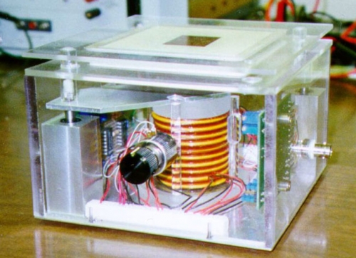
One solution to this problem is a mechanically active spiral patch antenna. In order to tune a broad range of frequencies, distances between the ground plane and the patch of up to 1 cm were needed. The design featured a unique combination of one static platform and one dynamic one. Since a high bandwidth, low stroke, and low power actuation system was needed the dynamic platform is actuated by piezoelectric RAINBOW (Reduced And INternally Biased Oxide Wafers) stack actuators. RAINBOW's are a type of piezoceramic actuator that is capable of relatively large deflections when compared to conventional PZT stacks. Various control techniques to include positive position feedback and lag control have been employed to counteract the effects of hysteresis and creep on the actuator. Since the use of metal components can degrade antenna performance, emphasis was placed on synergy in the design process.
A picture of this stack arrangement, as used in a current project, is shown below.
Two QuickTime movie files are available below, if you are interested in viewing the operation of this experimental structure. (If your browser is not configured to view ".mov" files, you can view these files using either QuickTime software or the standard Windows Media Player program.) Click on the two links below to view these files.
Click here to download ant1_patch.mov |
Click here to download ant2_patch.mov |
A similar methodology can be extended to rectangular microstrip patch antennas. The microstrip patch antenna is an ideal candidate when low profile, light weight, and small size is needed. They are rugged and can be manufactured easily using well known photo-etch techniques that are standard with modern electrical and microwave integrated circuits. A major weakness of the microstrip antenna is its narrow impedance bandwidth which typically ranges up to a few percent depending on the substrate dielectric constant, the dielectric thickness, and the geometry of the patch.
Frequency agility and bandwidth enhancement has been the subject of many studies to include the following: Embedding control elements in the patch, Proximity coupling techniques, impedance matching techniques, and the addition of a parasitic patch (The parasite patch is identical to the parent patch except it does not have a ground plane.) In this study, a mechanically active microstrip patch antenna is developed. The antenna consists of a microstrip patch antenna and a parasite that is mechanically actuated to vary its distance. The parasite is housed in a novel configuration that is actuated by RAINBOW stack actuators.
A third project uses the ferroelectric properties of Barium Strontium Titanate BaSTO to change the dielectric constant of the substrate between the two patches. The net effect is the same as varying the distance between the patch and the parasite.