A typical MR fluid has a maximum controllable yield stress of the order of 40 to 100 kPa, which is one order of magnitude higher than ER fluids. Hence MR fluids can be used for designing devices for high force applications easily. And one application is vehicle suspension shocks. The different configurations used for MR dampers are shear mode, flow mode, mixed mode and squeeze mode. Usually shear mode is used for low force applications. Hence MR dampers for vehicle suspensions are designed using the mixed mode or flow mode configurations. The MR damper developed at the Intelligent Structures and Systems Lab uses the mixed mode configuration. The MR damper has a built-in MR valve across which the MR fluid is forced. The piston of the MR damper acts as an electromagnet with the required number of coils to produce the appropriate magnetic field. Also the MR damper has a run-through shaft to avoid an accumulator.
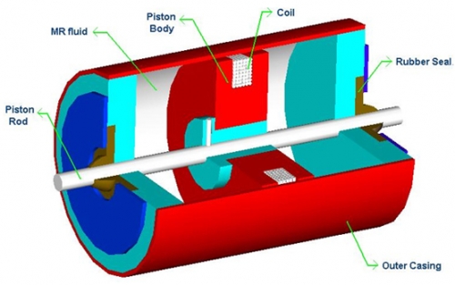
Fig 1. A 3-D cut view of the mixed mode MR damper
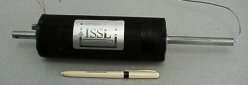
Fig 2. - Fabricated MR damper with test fittings
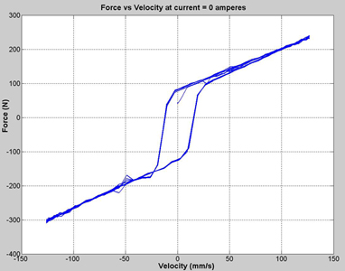
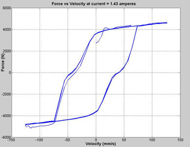
Fig 3. Force vs Velocity graphs for MR damper